
High-voltage test laboratory: on-site testing of 110–750 kV equipment
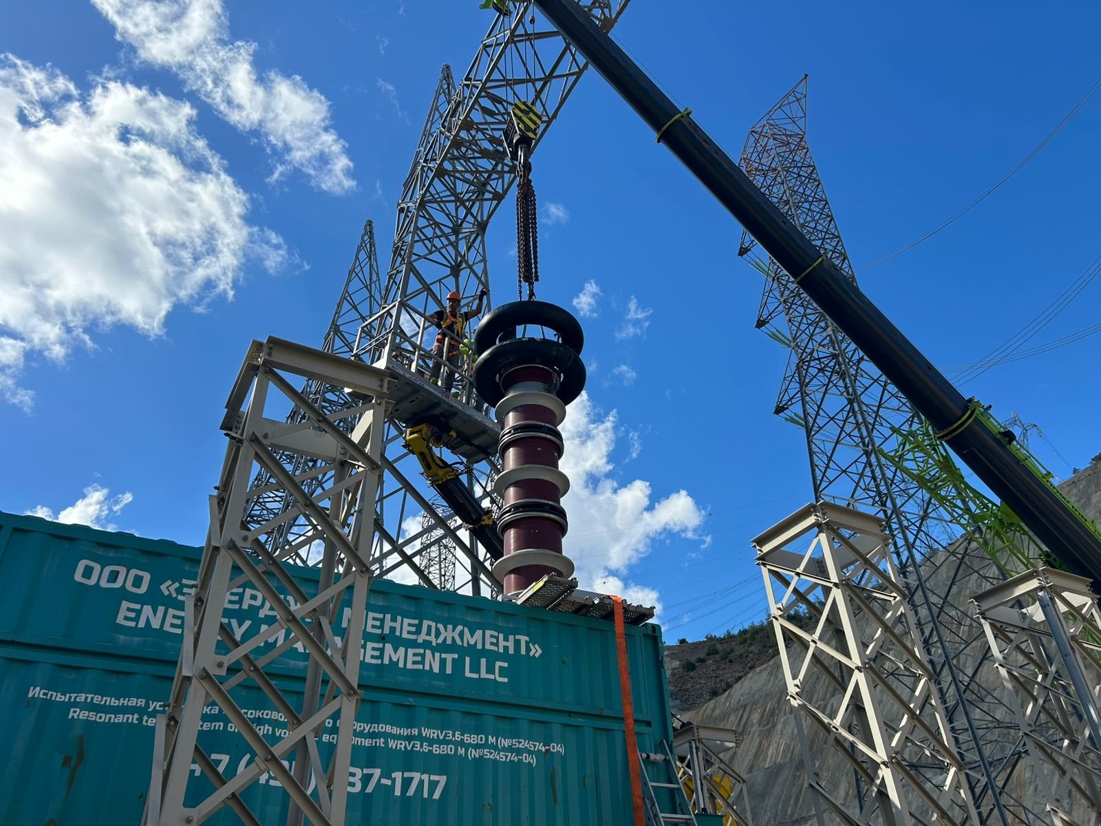
We test GIS, SF6 circuit breakers, disconnectors and current and voltage transformers at the installation site with two mobile resonant test systems, WRV 3.6/680 M and WRV 1.5/680 G. The laboratory is registered with Rostechnadzor (certificate No. 9834 of 20 December 2024). We travel to substations in Russia and the countries where we work.
What we test
- GIS
- SF6 circuit breakers
- Disconnectors and earthing switches
- Current transformers
- Voltage transformers
Mobile test laboratory
What the mobile set comprises
- two resonant test systems, WRV 3.6/680 M and WRV 1.5/680 G, in containers
- a partial discharge measuring system
- instruments for insulation resistance and circuit breaker timing measurement
- cabling and fittings for connection to the equipment under test
What the site has to provide
- space for the container next to the equipment under test
- power for the system from the site supply
- the section under test switched out and earthed, access under a work permit
- access to the primary terminals and the secondary circuits
The exact requirements are agreed when the test programme is prepared.
Where we travel
Substations and generating facilities in Russia, Belarus, Kazakhstan and Uzbekistan; we have worked at Rosseti sites, nuclear power plants and 220–500 kV substations under construction.
Response and call-out times are agreed with the customer for each request and kept as short as possible
How to prepare a visit of the mobile laboratory
For a visit, we need initial data on the equipment, and the site needs to arrange a work permit for the team. The more complete the request, the sooner the test programme and dates can be agreed.
What to include in the request
- equipment type and manufacturer, voltage class, number of bays or apparatus;
- scope of work: tests after erection, partial discharge measurement, circuit breaker checks;
- the single-line diagram and the boundaries of the sections under test;
- factory test reports and the manufacturer’s instructions with the on-site test values;
- site address, region and preferred dates.
Admitting the test team
Tests with a mobile test system are carried out under a work permit; in an energised installation, the team is admitted by the site’s operating staff (clause 39.2 of the Rules on Labour Protection in the Operation of Electrical Installations). Under these Rules, the person in charge of the work holds electrical safety group IV, team members group III, and the member guarding the test area group II (clause 39.3). The right to carry out tests is confirmed by a special-works entry in the knowledge test certificate. The equipment under test, the test system and the connecting leads are fenced off and marked with a “Testing. Danger to life” sign.
As the seconding organisation, we state the team composition in a covering letter and confirm the members’ electrical safety groups and their right to perform special works (clause 46.3 of the Rules). On arrival, the team receives induction and initial safety briefings and is familiarised with the installation’s electrical diagram (clause 46.4).
List of services
| Service | Equipment | More |
|---|---|---|
| Insulation strength verification | GIS, circuit breakers, transformers | GIS testing |
| High-voltage withstand testing | equipment for 110–750 kV | GIS testing |
| Partial discharge measurement | GIS, transformers | Partial discharge |
| Insulation resistance measurement of apparatus, secondary circuits and wiring up to 1 kV | all apparatus and circuits | — |
| Circuit breaker timing tests | SF6 circuit breakers | Circuit breaker service |
Rostechnadzor registration and permitted tests
Energy Management’s electrical test laboratory is registered with the Interregional Technological Directorate of Rostechnadzor, the Russian federal technical supervision authority: certificate No. 9834 of 20 December 2024. The certificate entitles the laboratory to perform acceptance tests and measurements of electrical equipment and installations rated up to 750 kV. The certificate card is on the company licences and approvals page.
Test installations (test laboratories) must be registered with Rostechnadzor under clause 39.1 of the Rules on Labour Protection in the Operation of Electrical Installations (Order of the Russian Ministry of Labour No. 903n of 15 December 2020). Before registering a laboratory, Rostechnadzor checks its test programmes and methods, staff qualifications, the verification of measuring instruments and the documentation for the test equipment. The certificate lets the customer check that the laboratory is authorised for the required test at the required voltage class.
| Equipment | Permitted |
|---|---|
| Switchgear | testing of GIS, metal-clad and outdoor switchgear up to 750 kV |
| Circuit breakers | testing of SF6, air-blast, oil and vacuum circuit breakers and load break switches up to 750 kV |
| Disconnectors | testing of disconnectors, automatic isolators and fault-throwing switches up to 750 kV |
| Instrument transformers | testing of current and voltage transformers up to 750 kV |
| Insulation and busbars | testing of suspension and post insulators, bushings and wall bushings up to 750 kV; busbars and connecting buses; bus ducts |
| Circuits up to 1 kV | insulation resistance measurement of electrical apparatus, secondary circuits and wiring |
The list is broader than the equipment described on this page. Testing of other equipment listed in the certificate is discussed on request.
The resonant test systems the laboratory uses for high-voltage tests undergo periodic certification every year, which confirms that they are fit for testing. The current certificates issued by PromMash Test Metrologiya LLC on 7 September 2026 are No. A-PMTM-086/08/2026 for the WRV1,5/680G system and No. A-PMTM-087/08/2026 for the WRV3,6/680M system; the certification interval is 12 months. The certificates and the laboratory registration certificate are on the “Licences and approvals” page.
Acceptance and periodic tests: what is the difference
Acceptance tests are carried out before new equipment is first energised, whether at a new or reconstructed facility or after a replacement. Periodic (in-service) tests are repeated throughout the service life, to a schedule and during repairs. Energy Management’s laboratory certificate covers acceptance tests.
| Criterion | Acceptance tests | Periodic tests |
|---|---|---|
| When | after erection, before operating voltage is applied | in service: during repairs and between them |
| Standards | PUE (Russian Electrical Installation Code), Chapter 1.8 (equipment up to 500 kV; it does not cover SF6 circuit breakers or GIS), manufacturer’s instructions; for GIS, also IEC 62271-203 | manufacturer’s instructions and industry standards, for example Rosseti standard STO 34.01-23.1-001-2017 “Scope and standards for testing electrical equipment” |
| What they look for | defects from transport and erection | insulation ageing and wear before they lead to a failure |
| Result | test report and statement of readiness for energisation | test report and comparison with previous measurements |
For consumers’ electrical installations, acceptance tests are required by clause 26 of the Rules for the Technical Operation of Consumers’ Electrical Installations (Order of the Russian Ministry of Energy No. 811 of 12 August 2022); defects found during them must be eliminated. These tests run alongside commissioning. Diagnostics, maintenance and repair of GIS and circuit breakers in service are described on the high-voltage equipment service page.
How GIS testing runs at the installation site
- 1
Why test GIS after erection?
Factory tests cover the bay, not the assembled switchgear: during site assembly contamination and defects in joints and SF6 connections are possible. A withstand test at the installation site finds them before operating voltage is applied.
- 2
How is the resonant system connected?
The container is placed next to the GIS and the reactor is connected to the terminal of the section under test and fed by the exciter through a matching transformer; earthed sections and disconnectors separate the volume under test.
- 3
How is the test regime chosen?
The frequency is tuned into resonance with the capacitance of the object — this way the system delivers the test voltage (up to 750 kV) from a low-power supply. The voltage is raised in steps according to the programme.
- 4
What is measured during the hold?
The partial discharge level and the leakage current; on a breakdown the system trips automatically and the section is localised.
- 5
What does the customer receive?
A test report with the regimes and results, a statement of readiness for energisation and recommendations where findings are recorded.
Test programme and report: what is agreed and what you receive
We agree the test programme with the customer before the visit and issue the report when the tests are complete. Both documents rely on the same standards: the equipment manufacturer’s instructions, the PUE or, for GIS, IEC 62271-203.
The test programme covers
- the boundaries of the sections under test and the connection diagram of the test system;
- the standards and methods applied;
- the test voltage, voltage steps and hold times;
- measurements during the hold and the acceptance criteria;
- safety measures and the procedure for admitting the team.
The test report typically states
- the laboratory’s details and registration certificate number;
- the object: name, type, serial number and location;
- the test date and conditions: temperature, humidity and, for SF6 equipment, gas density;
- the test voltage, its duration and the measured values;
- the measuring instruments and their verification dates;
- a conclusion on compliance with the standards and the signatures of the testers.
If a test reveals a finding, the report records the location and nature of the defect; once it has been eliminated, the section is usually retested.
Laboratory equipment
Block diagram of a resonant test system: power supply → exciter → matching transformer → variable inductance reactor → equipment under test; in parallel, voltage and partial discharge measurement.
Documents
Projects
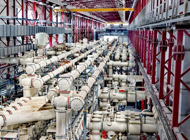
Akkuyu NPP: high-voltage testing of 400 kV GIS and SF6 bus ducts
400 kV GIS · 400 kV SF6 bus ducts

Arctic LNG 2: installation and commissioning of feed gas and boil-off gas compressors
feed gas compressors · boil-off gas compressors
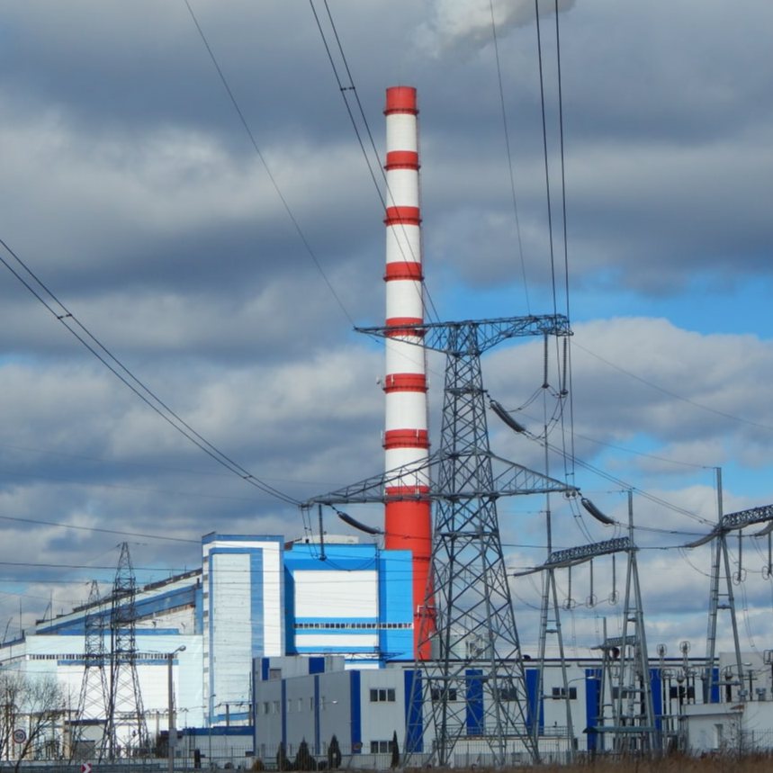
Belenergo: installation and commissioning supervision of 11 SGT-800 gas turbine units
11 × SGT-800 · full load in 15 minutes
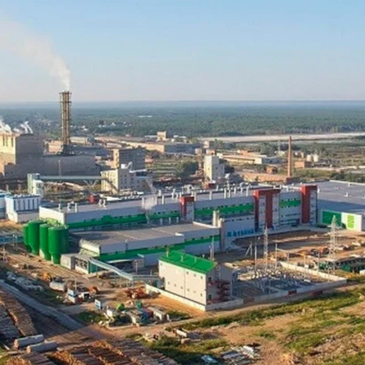
Ilim: board machine control system in Ust-Ilimsk
board machine of 600,000 tonnes a year · 2023

Knauf Petroboard: CHP steam boiler automation
steam boiler control system on SIMATIC PCS7
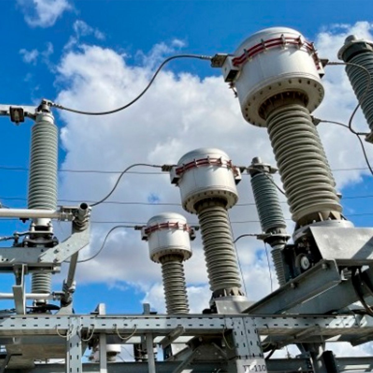
Rosseti: GIS for the 220 kV TsRP substation in Krasnoyarsk
1,920 sets of GIS equipment
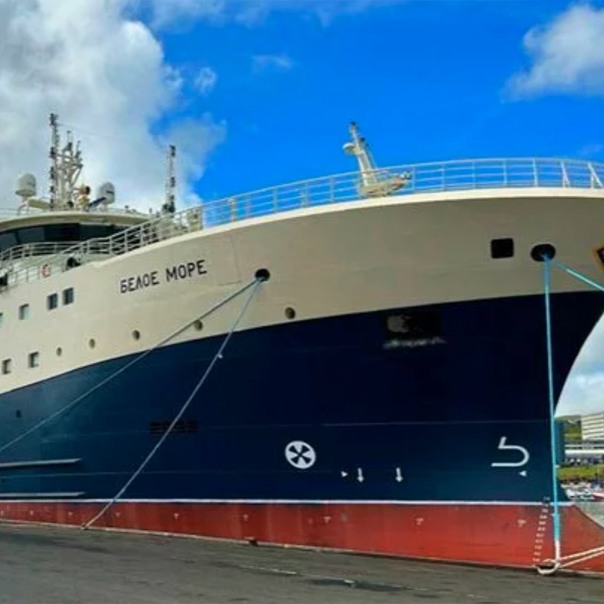
USC: electrical equipment for three fishing vessels
3 vessels · power distribution and monitoring system based on PMA300 · 2020–2023

Yamal LNG: eight SGT-800 gas turbines, boil-off gas compressors and 29 modular substations
8 × SGT-800 · 4 boil-off gas compressors · 29 modular substations
Example: 400 kV GIS testing at Akkuyu NPP
In 2025, the company’s specialists carried out high-voltage tests of the 400 kV GIS at the Akkuyu NPP construction site in Turkey:
- under a contract of 10 September 2025 — tests with partial discharge measurement of a bay and the busbars of two sections on the right-hand side of the 400 kV GIS;
- as part of the energisation of the right-hand section of the 400 kV GIS — tests with partial discharge measurement of the 400 kV GIS and 400 kV SF6 bus ducts.
Akkuyu Nuclear JSC recognised this work in two letters of appreciation, dated 4 November and 22 December 2025. Other work for nuclear power plants is described on the service and equipment for nuclear power page.
Questions and answers
Up to what voltage does the laboratory test equipment?
Up to 750 kV: two mobile <a class="term-link" href="../glossary/resonant-test-system/index.html" title="What is a resonant test system">resonant test systems</a>, WRV 3.6/680 M and WRV 1.5/680 G.
Why a resonant system rather than a test transformer?
A resonant circuit is tuned to the capacitance of the object and delivers high voltage from a low-power supply — the system fits into a container and runs off the site supply. A test transformer of that rating cannot be brought to a substation.
How long does GIS testing take?
It depends on the number of bays and how the switchgear is split into sections; we agree the programme and the schedule in advance. We do not promise timings up front — we state them after surveying the site.
Is the laboratory registered?
Yes: Rostechnadzor certificate of registration of the electrical test laboratory No. 9834 of 20 December 2024. It entitles the laboratory to perform acceptance tests and measurements of electrical equipment up to 750 kV.
Which documents do you issue?
A test report with the regimes and results, a statement of readiness for energisation and recommendations where findings are recorded.
Which equipment other than GIS is the laboratory permitted to test?
Under Rostechnadzor certificate No. 9834 of 20 December 2024: SF6, air-blast, oil and vacuum circuit breakers, load break switches, metal-clad and outdoor switchgear, disconnectors, automatic isolators and fault-throwing switches, current and voltage transformers, insulators and bushings rated up to 750 kV, as well as busbars and bus ducts. Insulation resistance measurement of apparatus, secondary circuits and wiring up to 1 kV is also permitted. Testing of equipment not covered on this page is discussed on request.
How do acceptance tests differ from periodic tests?
Acceptance tests are carried out before new or replaced equipment is first energised, to find defects from transport and erection; the standards are PUE Chapter 1.8 and the manufacturer’s instructions. Periodic tests are carried out in service, during and between repairs, to track insulation ageing; their scope is set by the manufacturer’s instructions and industry standards.