
Partial discharge measurement in high-voltage equipment
Partial discharges are local electrical discharges in insulation that do not bridge the whole gap between the electrodes; their level indicates the condition of the insulation. We measure it in GIS, circuit breakers and instrument transformers rated 110–750 kV: during acceptance withstand tests and in service — without an equipment outage.
Scope
- partial discharge level measurement in GIS, circuit breakers and instrument transformers
- measurement during on-site withstand testing
- in-service measurement at operating voltage without an outage
- location of the discharge source by bay and compartment
- insulation condition assessment and comparison with previous measurements
- measurement report and recommendations
When to measure partial discharge
Partial discharge is measured to find insulation defects that a withstand test alone will not reveal: after installation, after repairs that open the gas compartment, and in service, to compare with earlier results. The scope is set by the test programme, the manufacturer’s requirements and industry standards.
| Situation | Why measure | What the standards say |
|---|---|---|
| After installation of GIS and SF6 bus ducts | to find particles, contamination and assembly defects before the operating voltage is applied | the high-voltage withstand test of the main circuit insulation is accompanied by partial discharge monitoring (Rosseti standard STO 34.01-23.1-001-2017, clauses 19.3 and 21.3) |
| After repairs affecting the main circuit insulation | to check a compartment after it has been opened or an insulator or apparatus replaced | the same requirements; the test voltage may be reduced by agreement with the operator’s technical manager (STO, clause 19.3) |
| On commissioning, additionally at rated phase-to-earth voltage | to obtain a baseline for future comparisons | recommended by IEC 62271-203: this measurement helps decide whether maintenance is needed after a period in service |
| Between repairs | to track how a defect develops | for GIS, SF6 bus ducts and oil-filled current and voltage transformers of 110 kV and above — at the discretion of the technical manager (STO, clauses 19.10, 21.7, 10.1.11, 11.1.1.6) |
| On an alarm from the GIS monitoring system | to confirm the signal and find the compartment | a GIS monitoring system must measure partial discharge intensity and locate the defect (STO, clause 4.17.18) |
Measurement methods and what each one shows
Partial discharge is detected through three effects: a current pulse in the circuit, an electromagnetic wave inside the enclosure and ultrasound. In GIS the methods complement each other: the electrical method gives a value in picocoulombs, while the UHF and acoustic methods show where the defect is.
| Method | What it detects | Strength | Limitation |
|---|---|---|---|
| Electrical, GOST R 55191-2012 (IEC 60270) | current pulses through a coupling capacitor; the result is apparent charge in pC | the only method calibrated in pC; factory test limits are set in pC | sensitive to electromagnetic interference on site; does not show where the defect is |
| Ultra-high frequency (UHF, 300 MHz – 3 GHz), IEC TS 62478 | electromagnetic pulses inside the GIS enclosure, picked up by built-in or external sensors | the metal enclosure screens out external interference; the defect is located from the difference in signal arrival time at two sensors; suitable for continuous monitoring | cannot be calibrated in pC; external sensors on inspection windows and insulators are less sensitive |
| Acoustic (ultrasonic), IEC TS 62478 | elastic waves on the enclosure caused by discharges and particle impacts | unaffected by electromagnetic interference; pinpoints the defect within a compartment; good at detecting moving particles | poor at detecting defects inside cast insulation; equipment vibration interferes |
Readings from different methods cannot be converted into one another: UHF and acoustic signals depend on where the defect is and on the signal path to the sensor. Instead of calibration in pC, such systems therefore undergo a sensitivity check: an artificial pulse with the same signal as a discharge of about 5 pC is injected into the GIS to confirm that the adjacent sensor detects it (IEC 62271-203, Annex C; CIGRE TB 654). Results can be compared over time only if the same method and the same sensors are used. The method, sensor positions and confirmed sensitivity are recorded in the measurement programme.
How measurement proceeds
- 1
Programme
List of bays and apparatus; mode — at operating or test voltage.
- 2
Connection
Sensors on enclosures and bushings; the site background is measured separately.
- 3
Measurement
Recording of the level and pattern of discharges for each section.
- 4
Assessment
Insulation condition, source location, recommendations.
How to interpret the results
Results are assessed on three counts: the value against the limit, the change since the previous measurement and the signal pattern, which indicates the type of defect.
- Acceptance after installation or repair. GIS passes the test if there is no insulation breakdown and no partial discharge above the noise level (STO 34.01-23.1-001-2017, clause 19.3). For comparison, the factory test limit for GIS under IEC 62271-203 is 5 pC.
- In service. The trend matters more than a single value: a rise in pulse amplitude or repetition rate between measurements points to a developing defect. The result is therefore compared with the commissioning measurement and earlier reports.
- Signal pattern. The distribution of pulses over the voltage cycle, their amplitude and repetition differ from one defect to another.
| Source | How it shows | What to know |
|---|---|---|
| Moving metal particle, such as swarf left after assembly | clearly visible to the electrical, UHF and acoustic methods; acoustically heard as impacts on the enclosure | regarded as a high-risk defect because the particle behaves unpredictably |
| Floating potential: a shield or contact with no electrical connection to the conductor or enclosure | frequent pulses of high amplitude | points to a lost contact; the discharges recur until the contact is restored |
| Protrusion or burr on a live part or the enclosure | the signal resembles corona | usually found at the factory and rarely seen on site |
| Defect in a cast insulator: void, crack or delamination | low amplitude — well below 10 pC for voids smaller than 1 mm; discharges may start with a delay | hardly detectable acoustically — the electrical or UHF method is needed |
| Contamination or a particle on an insulator surface | surface discharges: the signal is usually noticeable but variable | a single particle on an insulator gives a very weak signal and is hard to find by any method |
The type of defect is determined from the combination of signs and, where possible, with two methods.
If the level exceeds the limit
An exceedance means that the defect has to be found and eliminated before energisation or before a failure. The procedure:
- Rule out external sources: corona on busbars and bushings, radio and welding interference on site; compare the signal with the background with no voltage applied.
- Confirm the signal with a second method and compare its pattern with typical defects.
- Locate the source: with UHF sensors from the difference in arrival time — to a compartment; with acoustic sensors — within the compartment.
- After installation or repair, open the compartment, eliminate the defect and repeat the withstand test with partial discharge monitoring.
- In service, repeat the measurement at a shorter interval, watch the trend and plan the repair before a failure occurs.
Defects found can be eliminated under our high-voltage equipment service for 110–750 kV: maintenance, repair and upgrades of GIS and SF6 circuit breakers.
What to prepare for the measurement
The more complete the input data, the more accurate the programme and the comparison of results. The customer should prepare:
- a single-line diagram and a list of bays, apparatus and feeders with their voltage class;
- factory test reports with partial discharge levels and the results of earlier measurements;
- details of built-in UHF sensors and the monitoring system, if any: sensor positions and connector types;
- for acceptance, the installation of the section under test completed and the compartments filled with SF6 gas to rated pressure, at which the tests are carried out (STO 34.01-23.1-001-2017, clause 19.3);
- data on in-service events: protection trips, monitoring alarms, SF6 gas analysis results.
Site requirements — space for the container, power supply for the test system, disconnection and earthing of the section, work permit — are listed on the high-voltage test laboratory page.
Who performs the measurements
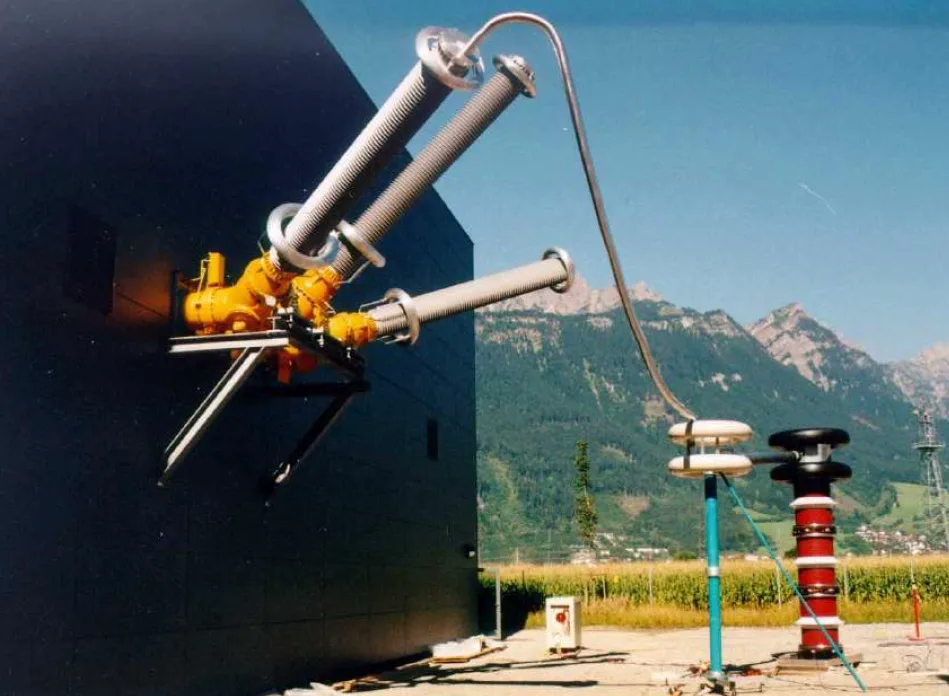
Measurements are carried out by the company’s own high-voltage test laboratory. It is registered with the Interregional Technological Directorate of Rostechnadzor (the Federal Service for Environmental, Technological and Nuclear Supervision): certificate No. 9834 of 20 December 2024 entitles the laboratory to perform acceptance tests and measurements of electrical equipment and installations rated up to 750 kV. The list of permitted tests covers GIS, SF6 circuit breakers, current and voltage instrument transformers, bushings and bus ducts. The test voltage is produced by two mobile AC resonant test systems, WRV 3.6/680 M and WRV 1.5/680 G.
Akkuyu NPP, 400 kV GIS. Under a contract dated 10 September 2025 the company’s specialists carried out high-voltage tests with partial discharge measurement of bay No. 13 and the busbars of two sections on the right-hand side of the 400 kV GIS. They then tested the 400 kV GIS and 400 kV SF6 bus ducts with partial discharge measurement during the energisation of the right-hand section of the GIS. Akkuyu Nuclear JSC recognised the work in letters dated 4 November and 22 December 2025; the first letter of appreciation notes the well-coordinated work of the team of test supervising engineers at the Akkuyu NPP site. What else the company does for nuclear power plants is described on the nuclear power service and equipment page.
Standards and guidelines
Measurement methods, limits and the scope of testing are set by the following documents.
| Document | Scope |
|---|---|
| GOST R 55191-2012 (IEC 60270:2000) | electrical method: measuring circuit, calibration, apparent charge, discharge inception and extinction voltages |
| IEC TS 62478:2016 | electromagnetic (HF, VHF, UHF) and acoustic methods, location of discharge sources, sensitivity checks |
| IEC 62271-203:2022 | GIS rated above 52 kV: tests, including the partial discharge limit for factory tests and on-site testing |
| GOST R 54828-2022 | general specifications for GIS rated 110 kV and above; in force since 1 February 2023, superseding GOST R 54828-2011 |
| STO 34.01-23.1-001-2017 (Rosseti PJSC) | scope and standards for testing: GIS (section 19), SF6 bus ducts (section 21), current and voltage transformers (sections 10 and 11) |
| CIGRE TB 662 and TB 654 (2016) | practical guidelines: use of unconventional methods; sensitivity verification of UHF systems for GIS |
Related pages
Questions and answers
Does the equipment have to be taken out of service?
No: in service, measurements are taken at operating voltage without an outage. During acceptance tests <a class="term-link" href="../glossary/partial-discharge/index.html" title="What is partial discharge">partial discharge</a> is measured during the withstand period.
What does the partial discharge level indicate?
The condition of the insulation: contamination, inclusions, defects in joints and insulators. A rise between measurements is a signal to investigate before a failure.
Which equipment do you measure?
<a class="term-link" href="../glossary/gis/index.html" title="What is GIS (gas-insulated switchgear)">GIS</a>, SF6 circuit breakers, current and voltage transformers rated 110–750 kV.
What does the customer receive on completion?
A measurement report for each section, an insulation condition assessment, source location and recommendations.
How does partial discharge measurement differ from a high-voltage withstand test?
A withstand test checks whether the insulation can hold the voltage without breakdown. Measuring partial discharge during that test reveals defects that do not yet cause breakdown but erode the insulation over time: moving particles, lost contacts, voids in insulators. That is why both are carried out together when GIS is tested.
How often should partial discharge be measured in service?
Under the testing standards (Rosseti standard STO 34.01-23.1-001-2017), partial discharge monitoring accompanies the GIS withstand test after installation and after repairs affecting the main circuit insulation. Between repairs, measurements are taken at the discretion of the operator’s technical manager, taking the manufacturer’s requirements into account; if the level rises, the interval to the next measurement is shortened.
Engineering team
High-voltage test laboratory