
On-site high-voltage testing of GIS
Our service test laboratory tests GIS, SF6 circuit breakers, disconnectors and earthing switches, current and voltage transformers rated 110–750 kV at the installation site. Mobile resonant test systems deliver test voltages up to 750 kV from the site supply; partial discharge is measured during the withstand period. On completion — a test report and a statement of readiness for energisation.
The laboratory is registered with Rostechnadzor: certificate No. 9834 of 20 December 2024.
Scope
- insulation withstand testing
- AC withstand testing with a resonant test system
- partial discharge measurement during the withstand period
- insulation resistance measurement of apparatus, secondary circuits and wiring up to 1 kV
- circuit breaker timing measurement
- division of the GIS into test sections and the test programme
- test report and statement of readiness for energisation
National standards for measurement, occupational safety and metrological assurance are observed.
What we test
| Equipment | Voltage | Measurements |
|---|---|---|
| GIS | 110–500 kV | withstand voltage · partial discharge · insulation resistance |
| SF6 circuit breakers | 110–750 kV | withstand voltage · timing · insulation resistance |
| Disconnectors and earthing switches | 110–750 kV | withstand voltage · insulation resistance |
| Current and voltage transformers | 110–750 kV | withstand voltage · partial discharge |
| Secondary circuits and wiring | up to 1 kV | insulation resistance |
Manufacturer names and designations are given to identify the equipment we service. Trademarks belong to their respective owners. Energy Management LLC is an independent service company.
How testing proceeds
- 1
Programme
Sectioning, voltage steps and hold times agreed with the customer.
- 2
Connection
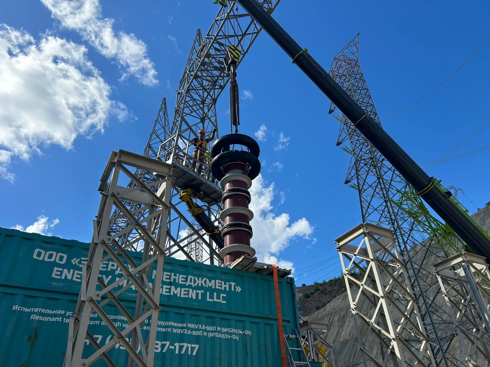
Container next to the GIS; the reactor is connected to the section bushing and fed by the exciter through a matching transformer; section isolated and earthed under a permit.
- 3
Resonance
Frequency tuned to the object capacitance; voltage raised in steps.
- 4
Withstand
Partial discharge and leakage current measured; the system trips automatically on breakdown.
- 5
Report
Settings, results, readiness statement, recommendations where defects are found.
GIS site acceptance test programme
On-site tests begin once erection of the GIS is complete. Their scope is set by the Russian national standard GOST R 54828-2022 (clause 9.2.8) and the manufacturer’s operating documentation; the industry scope and acceptance values for GIS tests are given in section 19 of the Rosseti corporate standard STO 34.01-23.1-001-2017 “Scope and Standards for Testing Electrical Equipment”. The programme is agreed between the manufacturer and the customer. The high-voltage test of the main-circuit insulation normally comes last: it starts when the GIS is fully erected, adjusted and filled with SF6 gas to its rated density.
| Check | What it confirms |
|---|---|
| Erection check against drawings | correct assembly, tightening torque of bolts and clamps, auxiliary and control wiring, operation of interlocks, monitoring, measuring and protection devices, heating and lighting |
| Mechanical operation | operation of circuit breakers, disconnectors and earthing switches to the extent set by the specifications |
| Gas tightness test | no SF6 leaks at any joint made on site; a leak detector may be used |
| Gas quality check | SF6 moisture content, measured five days after final filling; without this data, service voltage is not applied |
| Main-circuit resistance | quality of contact joints: values no higher than those permitted in the factory routine tests |
| Dielectric test of auxiliary circuits | insulation strength of auxiliary and control circuits |
| High-voltage test of the main-circuit insulation | no assembly defects, no damage from transport or erection, no foreign bodies; partial discharge intensity no more than 10 pC |
Of these checks, our high-voltage test laboratory performs the last one: the high-voltage test of the main-circuit insulation with partial discharge measurement. The full scope of our work is listed under Scope.
The resonant test system and the GIS: why capacitance matters
The capacitance of a GIS determines the test frequency, how voltage transformers are handled and how the installation is divided into sections. The general principle of resonant testing is explained in the glossary; for GIS it leads to three practical rules.
- Frequency depends on the size of the section. Capacitance grows with the number of bays and the length of busbars and bus ducts: the higher it is, the lower the resonant frequency. IEC 62271-203 draws on experience of tests at frequencies from 10 to 300 Hz. If the capacitance of a section is too high for the test system, the section is split.
- Voltage transformers. The magnetic flux in the core of an inductive voltage transformer is proportional to the ratio of voltage to frequency, so at a low frequency and a voltage above its rating the core saturates. The transformer is therefore either disconnected or tested together with the GIS at a frequency at which saturation does not occur — in practice usually 100–200 Hz.
- Limited consequences of a breakdown. On breakdown the circuit detunes, the voltage collapses and the energy released at the fault is limited. This is one of the reasons for dividing a GIS into sections: GOST R 54828-2022 lists it alongside limiting the capacitive load on the source and improving the detection of disruptive discharges.
The sinusoidal waveform and the low inherent noise level of the test system make it possible to measure partial discharge within the same test cycle.
Testing SF6 bus ducts
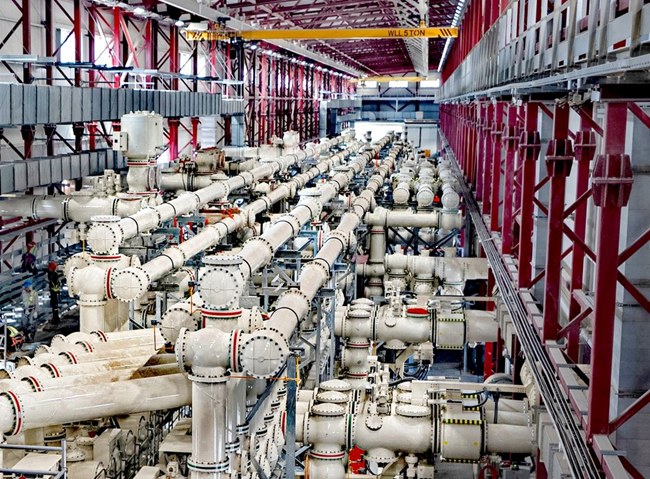
An SF6 bus duct is a conductor on support insulators inside an earthed metal enclosure filled with SF6 gas. Bus ducts connect a GIS to power transformers, SF6-to-air bushings and remote feeders. Under GOST R 54828-2022 bus ducts are part of the GIS scope of supply, and STO 34.01-23.1-001-2017 has a separate section 21 on test standards for 110–750 kV SF6 bus ducts. The company has experience of testing 400 kV SF6 bus ducts at Akkuyu NPP (see the next section).
How testing a bus duct differs from testing the bays:
- capacitance — a long bus duct adds capacitance, so the resonant frequency is lower and the reactor current higher. Bus duct lengths are taken into account when dividing the GIS into sections and selecting the test system;
- partial discharge — on straight runs an ultra-high-frequency (UHF) signal attenuates less than in the bays, so sensors on a long bus duct can be spaced further apart; the sensor layout is confirmed by a sensitivity check;
- section boundaries — a bus duct is tested as part of a GIS section or on its own; adjacent parts not under test are earthed.
Experience: 400 kV GIS and bus ducts at Akkuyu NPP
At the construction site of the Akkuyu nuclear power plant in Turkey, the company’s specialists carried out high-voltage tests with partial discharge measurement. Akkuyu Nuclear JSC recognised two pieces of this work with letters of appreciation:
- 400 kV GIS: bay No. 13 and the section busbars on the right-hand side of the GIS — work under a contract dated 10 September 2025; letter dated 4 November 2025.
- 400 kV GIS and 400 kV SF6 bus ducts — tests to enable energisation of the right-hand section of the 400 kV GIS; letter dated 22 December 2025.
In the first letter the customer noted “the well-coordinated work of the team of supervising test engineers at the Akkuyu NPP site” (translated from Russian). Scans of the letters are published under customer letters of appreciation; the second piece of work is described in the news item on energising the 400 kV GIS. What else we do for nuclear power plants is described on the service and equipment for nuclear power page.
Coordinating the test with the erection contractor and the manufacturer
The on-site test is a joint stage for three parties: the erection contractor, the manufacturer’s supervising engineers and the high-voltage test laboratory. To keep it on schedule, the following are agreed in advance:
- the programme — besides the sectioning, voltage steps and hold times, it sets the partial discharge criteria and the procedure in the event of a breakdown, including repeat testing of the section;
- readiness of sections — the checks in the table above have been completed for each section and the compartments are filled with SF6 to rated density;
- what is disconnected — cables, overhead lines, power transformers and surge arresters are usually disconnected for the test; voltage transformers stay connected only if the test frequency rules out saturation or they are rated for the test voltage;
- connection points — an SF6-to-air bushing or a test adapter for the reactor, and the positions of partial discharge sensors; GOST R 54828-2022 requires adapters for connecting test systems to be supplied with the GIS as specified in the enquiry data sheet;
- reconnection — after the test the disconnected components are refitted and checked: IEC 62271-203 warns that reconnection may introduce a new fault;
- extension of a GIS in service — the adjacent energised part is normally de-energised and earthed for the duration of the test.
What to prepare for a request
To draw up the programme and calculate the test settings we will need:
- the single-line diagram and GIS layout showing the erection stages;
- GIS type and manufacturer, rated voltage and insulation levels from the specifications;
- the manufacturer’s instructions listing the on-site tests — GOST R 54828-2022 requires the instructions to include such a list;
- lengths of SF6 bus ducts, the cable and overhead line connections, positions of voltage transformers and surge arresters;
- the erection and SF6 filling schedule;
- site access and personnel clearance requirements.
The mobile laboratory’s equipment and working procedure are described on the high-voltage test laboratory page; Rostechnadzor certificate No. 9834 of 20 December 2024 is listed under licences and approvals.
Projects and related pages
Questions and answers
Why test GIS after erection if it was tested at the factory?
Factory tests prove the bay, not the erected installation: contamination and defects in joints and SF6 connections can arise during site assembly. On-site withstand testing reveals them before service voltage is applied.
What does the site need to provide?
Space for the container next to the equipment under test, supply for the test system from the site network, isolation and earthing of the test section, a work permit, and access to the primary terminals and secondary circuits.
How long does testing take?
It depends on the number of bays and the sectioning scheme; the programme and schedule are agreed in advance. Response and call-out times are agreed with the customer for each request and kept as short as possible.
What voltage is applied to a GIS on site?
Lower than the factory test voltage but higher than the service voltage. IEC 62271-203 derives on-site test voltages from the rated insulation levels using a factor of 0.8 and sets a withstand time of 1 minute; GOST R 54828-2022 refers to GOST R 55195 and GOST R 55192. Exact values, steps and hold times are fixed in the programme agreed between the manufacturer and the customer.
Does a GIS need testing after repair or extension?
Every newly installed part of a GIS must be tested: GOST R 54828-2022 requires it. For repairs, the same standard provides for a dielectric test after medium and major overhauls, and IEC 62271-203 recommends one after major dismantling of compartments for maintenance. For an extension, voltage is sometimes also applied to the adjoining existing part so that all affected sections are covered.
Do you test SF6 bus ducts?
Yes. At the Akkuyu NPP site the company’s specialists carried out high-voltage tests with partial discharge measurement on a 400 kV GIS and 400 kV SF6 bus ducts; the customer recognised the work in a letter of appreciation dated 22 December 2025. Rostechnadzor certificate No. 9834 of 20 December 2024 lists testing of GIS in installations up to 750 kV and testing of bus ducts (busbar trunking).
Engineering team
High-voltage test laboratory