
110 kV gas-insulated switchgear: 145 kV bays
Gas-insulated switchgear for 110 kV networks: bays rated 145 kV, breaking current 40 kA, busbar and feeder rated current 3,150 A. Bay width from 800 mm, mass about 3 t, SF6 leakage no more than 0.1% a year, service life over 50 years. Supply, installation supervision, on-site high-voltage testing and service.
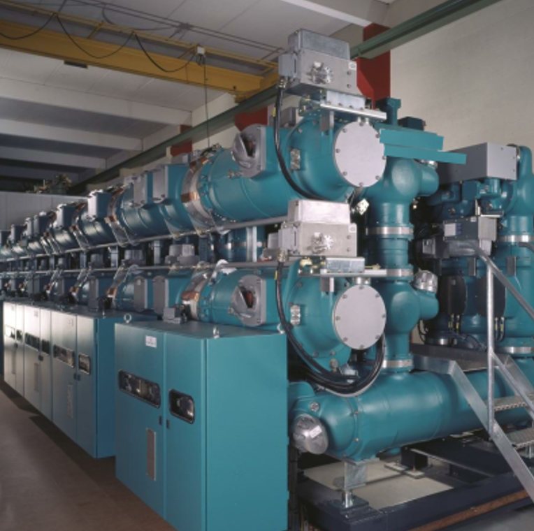
Key facts
- 110 kV network class → bay rated voltage 145 kV, frequency 50/60 Hz.
- Breaking current 40 kA, short-time current 40 kA for 3 s; busbar and feeder current 3,150 A.
- AC withstand test voltage 275 kV (1 min, 50 Hz), lightning impulse 650 kV.
- Bay width 800 mm with three-phase operation and 1,200 mm with single-phase; mass about 3 t.
- SF6 leakage no more than 0.1% a year; service life over 50 years; first visual inspection after 9 years.
- Motor-charged spring mechanism of the circuit breaker; indoor operation from −30 to +40 °C.
Bay data
| Parameter | Value |
|---|---|
| Rated voltagekV | 145 |
| FrequencyHz | 50/60 |
| AC withstand test voltage (1 min, 50 Hz)kV | 275 |
| Lightning impulse withstand voltagekV | 650 |
| Busbar rated currentA | 3,150 |
| Feeder rated currentA | 3,150 |
| Breaking currentkA | 40 |
| Short-time current (3 s)kA | 40 |
| SF6 leakage a year | no more than 0.1% |
| Bay widthmm | 800 (three-phase operation), 1,200 (single-phase) |
| Bay masst | about 3 |
| Circuit breaker mechanism | motor-charged spring |
| Ambient temperature°C | from −30 to +40 |
| Service lifeyears | over 50 |
| First visual inspectionyears | after 9 |
Composition and layout
- Bay
- circuit breaker, disconnectors and earthing switches, current and voltage transformers, busbars — in sealed earthed enclosures filled with SF6
- Operation
- three-phase (800 mm bay) or single-phase (1,200 mm) — to suit the substation scheme and automation requirements
- Connections
- cable terminations, SF6-to-air bushings for switchyards and lines, direct transformer connections
- Location
- indoors, from −30 to +40 °C; the bay mass of about 3 t simplifies floors and installation
- On-site testing
- after installation — high-voltage testing with a mobile resonant test system and partial discharge measurement
- Service
- SF6 density monitoring, mechanism maintenance; first visual inspection after 9 years
Which bays make up a 110 kV GIS
A 110 kV GIS is built up from bays according to the substation single-line diagram: each line, transformer, bus section or bus coupler circuit breaker and busbar voltage transformer has its own bay. The bay arrangement is set by the design; typical bays are shown below.
| Bay | Main equipment |
|---|---|
| Line | circuit breaker, busbar and line disconnectors, earthing switches, current transformers, a voltage transformer where required; cable termination or SF6-to-air bushing |
| Transformer | circuit breaker, disconnectors, earthing switches, current transformers; cable termination, SF6-to-air bushing or direct connection to the transformer |
| Bus section, bus coupler | circuit breaker, disconnectors on both sides, earthing switches, current transformers |
| Busbar VT | voltage transformer, disconnector, earthing switch |
Gas-tight insulating partitions divide the enclosures into compartments, each with its own SF6 density monitoring. This reduces the amount of gas handling when a single device is repaired.
Why GIS rather than an air-insulated switchyard
- 1
Immunity to the environment
Live parts are in sealed SF6-filled enclosures: dust, moisture, salt and precipitation do not affect the insulation.
- 2
Compactness
With bays from 800 mm wide, a 110 kV switchgear fits into a building on a fraction of the area of an air-insulated switchyard.
- 3
Seismic withstand
Rigid modules on common frames withstand seismic loads better than extended air-insulated structures.
- 4
Extension without outages
New bays are connected to the operating switchgear without interrupting supply to consumers.
- 5
Little maintenance
Leakage no more than 0.1% a year, first visual inspection after 9 years, service life over 50 years.
GIS or air-insulated switchyard at 110 kV: area, installation, maintenance
A 110 kV GIS takes up 25–30 times less space than an air-insulated switchyard of the same voltage class and needs less civil and installation work. The comparison concerns the switchgear itself: the area for transformers and access roads stays the same, so the substation as a whole shrinks by a smaller factor.
| Criterion | 110 kV GIS | 110 kV air-insulated switchyard |
|---|---|---|
| Area | 25–30 times smaller | open site with gantries and busbars |
| Foundations | few: modules stand on common frames | for apparatus supports and gantries |
| Design and installation | shorter: standard modules are assembled and tested in the factory and joined on site | assembly of apparatus and busbars on site |
| Maintenance | maintenance without removing the SF6 gas — on request or after 12 years; major repair — on request or after 25 years | periodic inspections, cleaning of external insulation |
The scope and intervals of work are described on the 110–750 kV high-voltage equipment service page.
Applications
Where it is installed
- 110 kV substations in urban areas and on industrial sites
- switchgear of captive power plants
- modular substations for remote and Arctic sites
- refurbishment of 110 kV switchyards without a substation outage
On-site installation and testing
Once the modules are joined, the GIS is checked and tested as a whole before energisation. The scope of tests after installation is set by IEC 62271-203; the sequence of work:
- evacuating the compartments and filling them with SF6;
- checking the gas tightness of the compartments and the SF6 moisture content, measuring the main circuit resistance, checking the operation of mechanisms and interlocks;
- high-voltage insulation testing with a resonant test system and partial discharge measurement under a programme agreed with the customer;
- test report and statement of readiness for energisation.
Installation supervision is provided under a separate contract and can be combined with the equipment supply. Testing is done by the company’s high-voltage test laboratory (certificate of registration with Rostechnadzor No. 9834 of 20 December 2024); the programme and site requirements are described on the on-site high-voltage testing of GIS page. The company’s specialists took part in the installation and commissioning of the GIS at the 220 kV TsRP substation in Krasnoyarsk.
Related
Documents
Source: 145 kV bay data come from the company’s current website; GIS advantages come from the category page.
Questions and answers
Why is a 110 kV bay called “145 kV”?
110 kV is the network voltage class; 145 kV is the <a class="term-link" href="../glossary/rated-voltage/index.html" title="What is the rated (highest) voltage of equipment">rated voltage</a> for which the bay’s insulation and switching devices are designed under the standards.
What is the difference between 800 and 1,200 mm bays?
Width and operation: 800 mm — three-phase operation with one mechanism, 1,200 mm — single-phase, with a mechanism per phase.
How is GIS tested after installation?
With high voltage at the installation site using a mobile resonant test system, with <a class="term-link" href="../glossary/partial-discharge/index.html" title="What is partial discharge">partial discharge</a> measurement; a test report is issued.
How often does GIS need maintenance?
SF6 leakage does not exceed 0.1% a year; the first visual inspection is due after 9 years, and the service life is over 50 years.
How many bays does a 110 kV GIS need?
As many as there are connections in the single-line diagram: one bay for each line and power transformer, plus bus section or bus coupler bays and busbar voltage transformer bays. The exact arrangement is set by the design. For a technical and commercial proposal, the number and type of bays are taken from the substation single-line diagram or the enquiry data sheet.
Expert in charge
High-voltage equipmentManufacturers’ names and designations are used to identify the equipment we supply and service. Trademarks belong to their respective owners. Energy Management LLC is an independent engineering company.